This article was published in Pharmaceutical Engineering Magazine. The basic concepts put forth are relevant to both SS and SU fermentors. ISPE Members can order high quality reprints of articles at the following link: https://ispe.org/pharmaceutical-engineering-magazine
Download the full article:
An Exhausting Solution for Fermentors
By: Ernest L. Stadler, P.E.
Introduction: All processes are generally “debottle-necked” to optimize productivity. Process improvement in microbial fermentation is no different. Batches are often “pushed” to achieve higher cell densities. This will increase productivity by improving product yield however it does require an increase in the cultivation time since the organism doubling time is fixed by the organism being used. Also similar trends exist to achieve higher cell densities in cell culture bioreactors. The length of a fermentation batch is usually limited by depletion of a growth component or lack of oxygen or lack of cooling. One very troublesome limitation that can lead to ending a batch prematurely occurs when the sterile exhaust filter becomes clogged from “wetting out” and / or “solids loading” on its surface. Loss of air flow brings about a quick end to respiration and the cells will begin to die. The proper choice of exhaust pathway components can deal with the variety of factors that tend to foul the exhaust filter element. The principles discussed here apply to both microbial fermentors and cell culture bioreactors, however microbial fermentations will be severely limited due to relatively higher gas flows when exhaust path design is not given proper consideration.
In general, the achievement of higher cell density will require more oxygen mass transfer for aerobic fermentations. This drives the need for higher aeration rates as well as higher agitation rates. In microbial fermentors, this can place a demand on the hydrophobic sanitary exhaust filter elements requiring them to remain unclogged for the duration of the batch. Extended operation will allow even the very last organism doubling to take place as the maximum cultivation time is achieved.
Exhaust Filter Elements: The customary material for sterilizing grade exhaust gas aseptic processing filter elements are 0.2 micron membranes comprised of expanded polytetrafluoroethylene (ePTFE) commonly referred to as teflon based on Gore™ material. An integrity test correlated to ASTM F838-83 bacterial challenge test would demonstrate the validity of the rating. The 0.2 micron rating refers to a membrane whereby validation testing has proven the filter as being capable of withstanding a microbial challenge. The challenge would demonstrate the membrane as being capable of withstanding 1 x 10⁷ B. diminuta organisms per square centimeter of membrane surface area.
This size exclusion is meant to prevent external adventitious organisms larger than 0.2 micron from entering the sterile boundary where they could establish themselves and contaminate a batch of potentially high dollar value product. Similarly the exhaust filter is expected to keep the microbes of interest inside the fermentor sterile boundary to protect the external environment. It should be noted however that a limited group of bacterial spores and viruses can be smaller than 0.2 micron. There has been some thinking that the size exclusion should be lowered to 0.1 micron but excess pressure drop and a propensity to clog quicker have deterred most users from specifying a membrane with a rating lower than 0.2 micron.
Now, due to the hydrophobicity of this filter element material, i.e. it resists wetting by water, the element itself has a finite operating time when it is presented with a very wet gas stream comprised of liquid fines and small solid particles. Herein lies the challenge when debating the correct treatment of exhaust gas leaving the fermentor. Remember that the exhaust gas is heavily saturated with moisture and is at or near 100% relative humidity. It is important to think about all of these effects with respect to where the culture is in its growth kinetics.
We commonly think of the batch as existing in one of four stages of growth(1), i.e. lag phase, exponential growth phase, stationary phase, and death phase. The following typical chart represents these phases over time in a growth curve having no specific quantification of number of cells:
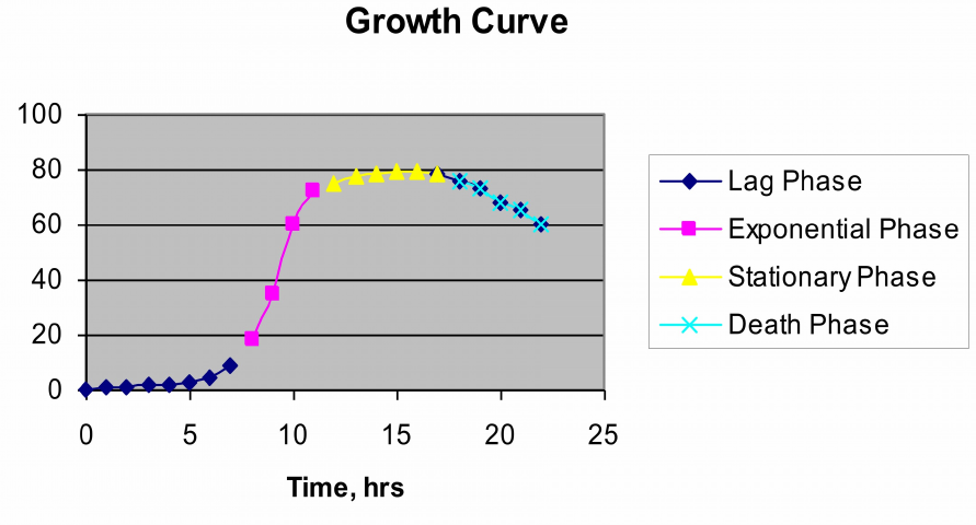
Figure 1. Typical Growth Profile
The exhaust velocity is highest near the end of the batch since oxygen demands and sparge gas flow are greatest at this point of maximum cell density. Exhaust gas at this high velocity will most likely have a high percentage of fine liquid particles as well as solids. Where do these particles come from?
Source of Particulates: A few common sources are:
Sparge gas bubbles breaking the surface interact with proteins in the broth and create foam at the surface. Foam bubbles at the upper most layer break open and discharge wet particles containing solid material carried up in the foam layer. High sparge gas flow rates exacerbate this problem but are necessary to support oxygen mass transfer.
High mixing speed contributes to an “agitated” liquid surface area. Aggressive mixing will cause splashing on the baffles and general surface vortexing all of which contribute to creating of liquid fines in the headspace. Often the surface of a highly aerated and agitated fermentation will appear to be boiling with the surface surging up and down in a seemingly random pattern.
Droplets of moisture dripping down from the top head and addition port dip tubes or other internal pipes act as small implosions when they hit the liquid surface level of the broth. Each droplet has an almost equal reaction in that a jet of liquid is sent up from the liquid level creating liquid fines as it breaks up. These small particles can be carried out thru the exhaust in the high velocity gas stream.
Liquids that condense in the exhaust pathway and reflux back to the fermentor must flow against the exhaust gas stream and eventually drip back into the headspace and onto the broth surface.
Vessel Head Space and Foam: It is not recommended to increase the working volume of a fermentor in an effort to gain higher productivity. The first consideration to deal with the myriad of liquid and solid fine particles generated is to have a vessel geometry with ample freeboard head space above the fully gassed liquid level. A good rule of thumb is to allow 25% of the total vessel volume dedicated to freeboard headspace above the unaerated liquid working level. This may need to be even higher in processes where very high aeration will greatly expand the working volume height. This “free” volume of space allows particle conglomeration by impingement and de-entrainment by settling. Many particles will drop back to the surface if they are in relatively low upwards velocity zone. Ample freeboard space above the working level is also necessary to deal with the formation of foam from the process. Foam level control is a very important first step to ensure long cultivation time. There are a variety of foam breaking techniques that will cut the foam layer and keep it from escaping the exhaust nozzle where the liquid and solid particles can very quickly clog the exhaust filter bringing the batch to a screeching halt. These include the spurious addition of antifoam agents to the batch, addition of electro-mechanical foam breakers (slingers or disk stacks), or addition of external foam separation devices.
Foam breakers can be installed in the headspace to collect the foam and direct it back to the vessel side walls where the liquid will run back down the vessel wall into the liquid broth. The function of these electro-mechanical devices is to protect the fermentor vessel exhaust nozzle from being filled with a slug of foam. Foam is the single largest contributor to rapid clogging of the exhaust filter element with resultant loss of gas flow. Another type of device that can be considered is an external vortex style separator to obtain a relatively moisture free gas stream leading to the exhaust filter.
The Great Debate: The most debated area and one where experience brings a variety of solutions is how the exhaust path piping and components are treated between the fermentor broth surface level and the inlet of the exhaust filter housing. As in all of engineering design, first principles must apply and the simplest solution that will do the job is usually the most effective. However sometimes complexity must increase, when pushing the limits of conventional practice. The resultant productivity improvements can only be achieved by proper application of additional components. Let’s start by building a simple system and establishing a path that will allow successively longer cultivation times to understand how the complexity can increase.
Batch: Simple
Aeration: Low
Agitation: Normal