This article was published in Pharmaceutical Engineering Magazine and won Article of the Year. Although thinking has changed regarding vessel geometry, hemishperical bottom heads, and impeller tip speeds, much of the information remains relevant today! ISPE Members can order high quality reprints of articles at the following link: https://ispe.org/pharmaceutical-engineering-magazine
Download the full article:
Dual Purpose Fermentor & Bioreactor? A Capital Quandary
By Ernest L. Stadler, P.E.
Abstract
A microbial fermentor or cell culture bioreactor optimized for a single intended purpose will always provide the most cost effective solution to production needs. This is not always possible with the increasing need for multi-product facilities having greater flexibility for adapting to various processes. Many major clients using this type of equipment consider investing in dual purpose units up front to allow for easier change over from microbial to mammalian cell culture operations. This article examines the design considerations for each and compares the trade-offs required to manufacture a multi-purpose unit.
Introduction
Many pharmaceutical and biotechnology manufacturers in the process of expanding their pilot or production facilities are concerned with the preservation of and proper utilization of capital to support their expected growth and future product mix. It is standard practice for these therapeutic product manufacturers to question the rationale behind their investment in a $20 to $40 million dollar plant. One scenario says, “How can I get the most versatility from my investment with the relative uncertainty over the future product mix?”
Since the scale-up of their process always requires a fermentor or bioreactor train, the question often arises “Should we invest in a dual purpose fermentor/bioreactor and what are the trade-offs affecting this decision?” For the purpose of this discussion I will use the generally accepted industry perception that a fermentor is used to incubate fast growth microbes (0.5 to 4 hour doubling times) with high oxygen mass transfer requirements necessary to yield high cell densities in batches running from 18 to 48 hours from inoculation to harvest. Harvesting will generally commence when the cell growth, and thus product yield, have become limited by lack of oxygen, substrate, nutrients, or cooling to maintain temperature control. By contrast, a bioreactor is used to incubate mammalian, insect, or plant cells with relatively slow growth rates (20 to 30 hours doubling time) that require small amounts of oxygen, are shear sensitive, and are produced in continuous culture that can run for 30 to 40 days or until aseptic operation can no longer be maintained.
These two classes of cell producing equipment dictate a vast difference in design when optimizing for one or the other type of bioprocess. Cost to manufacture is greatly influenced by the specific design requirements. The “capital quandary” facing the owner of the facility is to determine which case to design for. The owner must also decide if it is wise to invest in a dual purpose unit which could easily produce microbes or mammalian cells over the 15 to 20 year design life of the plant. Since the installed cost of the fermentors and/or bioreactors may represent the largest capital cost of all the bioprocess equipment, usually about 5 - 7%, a dual purpose train which may be about 6 - 8% of the total capital requires an additional $400,000 investment on a $40 million facility.
This is good news for the manufacturers of fermentors and bioreactors who are willing to serve it up “Burger King” style and have a sincere desire to fulfill the “have it your way” motto. The wisdom and risk of purchasing a dual-purpose bio-ferm-reactor can only reside with the pharmaceutical or biotechnology company making the decision. Their real issue is to determine if a major future product shift might drive their process from microbes to mammalian cells or vice versa.
The basic differences that dictate cost and functionality of a unit can be broken down into discrete areas as follows:
Vessel Considerations
Geometry
Ports
Finish
Agitator Design
Gas Supply Management
Exhaust System
Automation and Control
SIP and CIP Considerations
For this discussion I will compare a typical 1000 Liter total volume (Vt) fermentor which is required to operate in the future as a bioreactor. This dual purpose unit will be evaluated against (2) separate designs optimized for either fermentation or mammalian cell culture processing. By understanding the trade-offs, it will become apparent that the designer’s dilemma is to satisfy both requirements with the most elegant design which is usually the most cost effective solution.
Vessel Geometry
The overall vessel inside height to inside diameter ratio for a fermentor is usually 2:1 and can be as high as 3:1. A dished top and bottom head are common. Side wall heat transfer surface (HTS) is usually sufficient at this scale for removal of metabolic and agitator heat. Cooling is the predominant mode under temperature control and heat loss through the uninsulated bottom head is not of serious consequence. Batches or fed-batches are initially filled to a high level and are operated at maximum capacity for the duration under highly aerated conditions (except for anaerobic fermentations). Adequate “free board” headspace above the static liquid level is necessary, allowing for increased volume from air hold-up and management of foam build-up. Most fermentors are designed for a static fill of 75% which means that the working volume for our 1000L fermentor would be 750 liters maximum.

Figure 1. High vs Low L/D
An optimized 1000L Vt bioreactor would look quite different. The inside height to diameter would be closer to 1.5:1 resulting in a shorter vessel with a larger diameter. Figure 1 shows an exaggerated comparison of a high and low L/D vessel. Dished bottom and top heads are used; however, some cell culture processes are scaled-up on the basis of vessels with hemispherical bottom heads. This geometry is quite costly especially since bioreactors should always have thermally insulated bottom heads with heat transfer surface (HTS) incorporated. Mammalian cells quite often have to be warmed, i.e. heat added to the jacket, for precise temperature control to optimize growth. In addition, bioreactors often need to operate at very low levels so heat transfer and temperature control via the bottom head can be important. Since aeration rates are low and foaming not a problem, a 1000L Vt bioreactor could operate at 80 to 85% fill, i.e. 800 to 850 liters static liquid level. The height of the side wall HTS would have to be adjusted accordingly.
A dual purpose vessel would have to be designed for the fermentor case in terms of vessel ratio and heat transfer cooling capacity with the added cost of HTS and insulation on the bottom head. The temperature control loop piping would also have to be sized for the higher circulating flow rates and jacket nozzle sizes. Furthermore the heat exchanger would be sized to cool properly at maximum microbial cell density when the metabolic heat load is at its highest.
Vessel Ports
Fermentors typically have fewer ports than bioreactors and some of the ports are larger in size to accommodate higher gas flows, larger agitator shafts, and higher coolant recirculation flow rates. Bioreactors often have more instrument ports due to redundancy and specialty probes. Since they can operate for long periods, dual pH and pO2 probes are common to avoid losing a run due to probe failure.
Dual purpose units must consider including all of the necessary ports with the appropriate sizeing to accommodate successful operation in either mode. Vessel costs are usually driven upward to accomplish this versatility.
Vessel Finish
Much can be said about finishing vessel internal and external surfaces to a mirror like quality. Following mechanical polishing with electropolish (EP) results in great aesthetic beauty, but this comes at a great price. It is important to define the interior finish required for the process and the external finish required to satisfy wash-down needs (or perhaps aesthetics!). The operations required by the vessel fabricator to achieve mirror like finishes are labor intensive and must be performed in sequential steps. The more steps, the more the cost.
Cost effective fermentors can be constructed of pre-polished flat plate with external welds ground smooth ( as opposed to being ground flush). This is followed by glass bead blasting on the exterior to achieve a uniform appearance (about 30 Ra). More importantly, the interior surfaces must have welds ground flush with adjacent metal followed by mechanical polishing to at least a 20 to 25 Ra surface to facilitate cleaning and reduce the ability of microbes, spores, and proteins to adhere to the surface. This surface is typically adequate for fermentors with 2 to 2 ½ turn-arounds per week with effective cleaning cycles between each batch. Electropolishing is optional and when employed smoothes the surface to 15 to 20 Ra. In addition, EP provides the benefit of removing any corrosion products and forms a new protective oxide layer on the metal surface. This is the superior method of desensitizing the surface compared to passivation.
Turn-around for bioreactors on the other hand may be every 30 or more days. It is this extended aseptic operating cycle that dictates improved surface finishes. A fast growing microbe that contaminates a mammalian cell culture can overtake the batch and ruin it in short order. Mirror like surfaces inside the vessel are easier to clean. Mechanical polishing in the range of 10 to 15 Ra are commonplace and electropolishing to achieve single digit Ra finish is the norm. It is also my opinion that bioreactor suites producing high value therapeutics need to give the outward appearance consistent with the sterile environment they operate in. Highly polished external surface finishes look aesthetically pleasing and are easier to wash down when maintaining a clean room environment.
Agitator Design
The task of the agitator in a fermentor is to create a well mixed vessel from top to bottom assuring homogeneity of the combined media components. More importantly it provides a means of creating and dispersing small air bubbles to facilitate good oxygen mass transfer. The greater the air to liquid interfacial surface area present, the more oxygen can be driven into solution where if will be taken-up by cells during respiration. A secondary effect is to provide circulation against the vessel wall where heat transfer takes place for effective temperature control. This approach requires multiple radial “Rushton” style turbine impellors with relatively high tip speeds (1200 to 1400 ft/min) and the appropriate gassed horsepower (Pg) to achieve the oxygen transfer rate (OTR) needed. Other types of impellors and/or impellor combinations may be used as evaluated on a case by case basis for each specific fermentation process. Vessel baffles are important to yield the required degree of agitation since they aid in imparting shear to the fluid from the velocity head and radial flow leaving the impellor blades. Lack of baffles would result in a vessel having the entire fluid mass vortexing. In this case the impellors would be ineffective in shearing the liquid therefore little power would be imparted. Baffles also serve to provide up and down circulation paths which aid in top to bottom mixing and result in many secondary eddys and flow paths all of which aid in oxygen mass transfer.
The typical bottom centerline mounted agitator flange must be sized to accommodate the seal housing and shaft size required to transmit the torque while providing for low shaft deflections. This is important for smooth vibration-free operation. Top centerline mounted drives are preferred by some, particularly where the media has abrasive particles that can damage mechanical seal faces. Top drives generally require larger diameter shafts since the shaft is longer. This must be taken into account during the shaft critical speed analysis. In addition top drives require that the vessel head be reinforced adequately to support the drive and withstand any dynamic forces and moments.
By direct contrast, bioreactors need only slow, gentle mixing. Mammalian and other eukaryotic cells are shear sensitive to varying degrees. Being slow growers, their oxygen demand is low. Efficient mass transfer from the agitation system in not a critical concern. A top or bottom angled drive with single low shear, 45° pitched blade impellor running at low tip speeds (100 to 200 ft/min) will very nicely do the job. Baffles in the vessel are not necessary since the 15 to 20 degree angled drive breaks up symmetry in the mixing pattern to achieve top to bottom turn over. A vertically offset drive as shown in Figure 2 can also have the same effect. Baffles would provide additional unwanted shear and are best left out. Slow speed shafts and low horsepower drives are the norm. Shaft critical speed concerns are not of consequence.

Figure 2. Agitator Position
The dual purpose design must of course accommodate the high speed, high horsepower agitator in such a way as to also permit low speed operation with a low shear impellor. Removable baffles would allow one baffle to be left in the vessel to assist in breaking up the vortexing flow pattern - the result of the impellor rotating on the centerline mounted drive shaft. Since the vessel geometry favors a 2:1 ratio, the higher liquid height would necessitate more than one low shear impellor. A dual speed motor can provide the high speed range for microbial operation and a lower speed range for the low shear operation. The Variable Frequency Invertor (VFI) should be sized to allow long term operation at the low speed to avoid overheating of the motor. VFI rated motors are available with fixed speed cooling fans to assist with this problem.
Gas Supply Management
A microbial fermentor has a relatively simple inlet gas management system requiring only a single sterile filter. This provides air for organism respiration by delivery through a sparger to the bottom of the vessel. Often, to achieve high oxygen transfer rates, the air is supplemented with oxygen. In either case a separate overlay filter is not required. The sparger can be a single orifice type which relies totally on the radial turbine impellors for gas dispersal, or it can be a ring type with multiple orifices to aid in the gas dispersal. The purpose of the gas dispersal is to create a high air bubble surface area to liquid volume ratio which increases the rate of mass transport of oxygen across the interfacial area. The oxygen must be dissolved in the liquid to be available for cell metabolism. Microbial cells can be cultured to relatively high densities and growth is often limited by the availability of oxygen. Figure 3 shows various types of sparger elements.
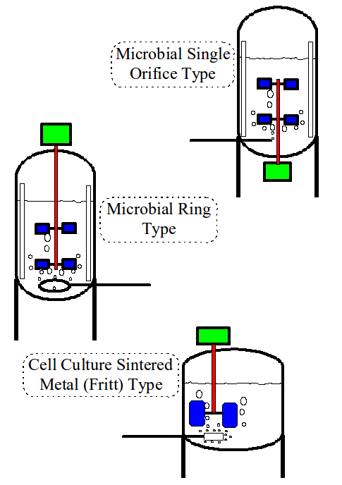
Figure 3. Sparger Types
Microbial air flow rates can be substantial, in the range of 1 to 2 vessel volumes per minute (VVM). The sparge filter, sparge orifice(s), and supply piping must be adequately sized to deliver this flow with a reasonably low pressure drop.
Excess bubbles, bubble size, and bubbles breaking the liquid surface do not present problems for microbial organisms which are not shear sensitive. Gas bubbles breaking the liquid surface do however present foaming problems. The presence of enough foam to enter the exhaust gas path will quickly clog the sterile filter, air flow will cease and the batch must be terminated to correct the problem. Foaming is readily dealt with using a foam level sensing probe which in turn controls liquid antifoam additions or an electromechanical foam dispersing device.
In contrast, the bioreactor has completely different gas management needs. The number of gasses required is more and flows are low, .001 to 0.1 VVM typically. Due to the relatively slow growth of mammalian cells the oxygen transfer demands are far less than that of a microbial fermentation. A major source of cell death is due to the inherent shear sensitivity. Gas bubbles bursting at the liquid surface and cavitation bubbles formed at high velocity areas of the impellor such as trailing tip vortices are leading sources of shear. These bubbles will collapse and implode as soon as they reach a lower velocity (hence higher local pressure) region and the implosion forces will also destroy mammalian cells.
The simplest way to assure the availability of sufficient oxygen for cell metabolism while minimizing the number and size of bubbles is to cut back on the total flow of air by enriching it with oxygen. In addition to this, many dissolved oxygen control strategies will require that air and oxygen flow be controlled into the vessel headspace via an overlay port with separate sterile filter. During the early growth phase of the culture, when cell density is quite low, oxygen transfer at the liquid surface area is sufficient for metabolism. This method delays the point at which gas must be routed to the sparger. Sparger designs for mammalian cell culture are usually porous sintered metal or stainless steel mesh. Pore size is usually in the range of 5 to 15 micron and the low flows will provide a nice source of fine bubbles that quickly dissolve into the culture medium to make the O2 available for cell metabolism.
Another gas used for bioreactors is CO2 which is used to control the carbonate balance (pH control) in lieu of liquid acid additions as for a fermentor. N2 is also often used to strip out oxygen during control of the dissolved oxygen level in the event that too much oxygen is sparged into the liquid. In all cases these gas flows are small due to the slow growth nature of the cells and the relatively low cell densities that can be achieved.
For a dual purpose unit the gas line and filter sizes must accommodate the maximum sparge flows that will be encountered during fermentation. In addition the supplemental gas supply lines and the overlay line with extra overlay filter must be in place in the event they are required for use as a bioreactor. It is relatively easy to design the sparge elements to be removable so various types are interchangeable to match the required performance.
Exhaust Gas System
The outlet line for a microbial fermentor must be sized to handle the volumetric gas flow of all gasses leaving the vessel headspace. This is predominantly non-utilized air (oxygen) and CO2 liberated during cell metabolism along with some water vapor due to the saturated conditions that exist in the headspace. Fine water droplets (mist) can be present in the exhaust gas as well as some degree of undissolved solids from the media. Most of the water mist is generated during violent agitation and at high air flows as the fermentor batch nears the peak of the cell growth phase.
The exhaust line will frequently have a condenser to reflux liquid and solid particle carryover back to the fermentor vessel. This method helps prevent the sterile hydrophobic exhaust filter from clogging. An alternate method is to include a heater upstream of the filter to vaporize the liquid fines there-by preventing the filter from wetting out. Solid particles may still accumulate and can bake-on the exhaust heater surfaces.
The critical control element for maintaining the vessel pressure setpoint during control is the back pressure control valve. This can be a rather large device when its Cv is sized for 1 to 2 VVM gas flow rates. Typical turn-down for a broad pressure control range is about 20:1. Even linear trim valves control pressure best in the 10% to 90% range of maximum flow. Fermentors usually operate in the 5 to 20 psig pressure range when increased pressure is used to increase oxygen mass transfer. The higher end of this range should be avoided due to upsets in the carbonate balance. Most fermentations are run at a pH setpoint near 7.0. CO2 gas is four times more soluble than O2 and excess CO2 concentration and the formation of carbonic acid can become a negative issue as fermentor pressure is increased.
Exhaust line and filter size for a bioreactor are much smaller than for a fermentor due to the low gas flows. A condenser or heater are not required since the non-violent agitation, lack of foam, and low gas escape velocities at the liquid surface do not create liquid mist with solid particle carry-over. Figure 4 shows a comparison between the two exhaust systems. The low gas flows result is much smaller size (i.e. lower Cv) for the back pressure control valve. Bioreactors are often operated at atmospheric pressure and rarely rely on increased pressure to aid in oxygen mass transfer.

Figure 4. Exhaust Systems
Clearly a dual purpose unit would have to be designed for the large line sizes and additional components required to successfully operate as a fermentor. One could build a case for installing two back pressure regulators, one sized for high gas flows and one sized for the low flow case. As a bare minimum the valve fittings should be sized to allow the two different valves to be interchangeable in the exhaust line with the proper one being installed for the appropriate gas flow required. It may be possible to install a valve that allows easy changing of the trim from a high Cv to a low Cv which could accommodate both cases.
Automation
The number of sensors and control parameters for a typical fermentor will vary. However, there are a few basic control loops that will always be present. The number of control loops installed greatly influences the complexity of control and the overall cost of automation. A fermentor will typically have one (1) mass flow controller sized for the appropriate airflow, automatic pressure control, automatic agitator speed control, a single pH probe and port for pH control, a single pO2 probe and port for dissolved oxygen control, and a single foam probe for control of foam. Fermentor runs are short (a few days) and the risk of losing a batch from a failed pH or pO2 probe is relatively low therefore single probes are usually sufficient.
pH is controlled via the addition of liquid acid or base. A delivery system with the appropriate resterilizable addition ports, addition cans, pumps or overpressure transfer systems, and transfer lines must all be in place to achieve safe and effective pH control.
Dissolved oxygen control is generally cascaded using pressure, agitator speed , air flow, and or nutrient feed with-in predetermined limits to increase oxygen mass transfer as the oxygen uptake rate (OUR) from organism metabolism increases throughout the batch. Since pressure can be used to increase the oxygen transfer driving force, automatic back pressure valves are utilized to allow for PID loop control.
The typical bioreactor will have more complexity than a fermentor primarily due to the increased number of gasses required and spare pH and pO2 probes. Installed spare probes avoid having to shutdown should one of the primary probes fail. . This is desirable since these units can run for several weeks uninterrupted. Another method that may be used in lieu of dual probes is to install a retractable resterilizable probe holder which allows for the possibility to change a defective probe mid-run. The multiple gas flows to both the sparge and overlay ports can require the use of up to six or seven mass flow controllers which greatly adds to the overall cost of automation.
Automation is an area where designing a dual purpose unit can get a bit messy yet not impossible. Variations in control strategy from fermentation to mammalian cell culture require the use of a flexible control system architecture that allows the user to easily change recipes when campaigning a cell culture vs. microbially expressed product. A dual purpose unit must have all of the control elements and loops present to run in either mode and a further complication is that the loops may require different tuning for each mode of operation. A good example of this would be control of vessel pressure. In the microbial case the air flow is high and one particular set of PID (proportional, integral, and derivative) tuning constants would provide for stable control with good response in the normal operating range. Trying to operate this loop with the same control tuning constants at low air flow and low pressure would probably not be possible unless a completely different set of tuning constants were invoked.
Another area that presents unique problems is the dissolved oxygen control loop. Dissolved oxygen control for fast growth microbial fermentation would behave quite differently than for a mammalian cell culture with slow doubling times. Having the ability to download recipes and changes in tuning parameters to a local controller from a central SCADA (supervisory control and data acquisition) system makes the task merely an SOP issue.
SIP/CIP
Fermentors are usually SIP’d (steam-in-place) with the vessel full of a previously prepared media formulation. This media is not sensitive to the “cooking” that occurs when sterilized at 121° C and held for 30 minutes. If there are any heat labile components in the formulation, they are added after the media is cooled to normal incubation temperature. Media components will however caramelize and “bake-on” the vessel sidewalls if sterilization temperature is too high or held too long. The control system for automatic SIP will sequence all valves to properly heat-up, hold at temperature, and cool-down the vessel contents while sterilizing all critical paths including the sterile filters and addition ports.
By direct contrast, a bioreactor is typically SIP’d empty since the media components are heat labile and would be seriously degraded during a full vessel sterilization sequence. The media, consisting of serum, amino acids, vitamins and other nutrients, is generally transferred to the empty previously SIP’d bioreactor under pressure transfer through hydrophilic 0.2 micron absolute sterilizing filters.
There are minor variations as to how the valves and paths would be sequenced to achieve an empty vessel sterilization compared to a full vessel sterilization. The dual purpose unit would require the necessary hardware and valve sequences programmed into the control system to allow the user to choose between a full or empty SIP.
CIP (clean-in-place) issues for the fermentor are more significant than for a bioreactor. Fermentors internals are difficult to CIP due to the flat and/or hidden surfaces present on the baffles, multiple radial turbine impellors, dip tubes, ring spargers (if used), and numerous ports on the top head. Multiple top head sprayballs are generally required as well as spray patterns that hit the underside of the turbine impellor disks. A bioreactor with single low shear impellor, angled drive shaft, and no vessel baffles presents a much simpler task for complete coverage from the sprayballs in the top head. In many cases a single sprayball will do the job.
In either case, fermentor or bioreactor, the external CIP paths that must be cleaned (i.e. sparge, overlay, exhaust, addition lines, harvest, etc.) are about the same in number and complexity. The simple fact is that all lines having product contact within the sterile envelope must be properly CIP’d. The dual purpose unit would have to be designed for CIP of the most complex set-up (i.e. fermentation case). The CIP validation testing should be performed with both the fermentor and bioreactor configurations to verify that acceptable cleaning takes place. This extra effort both in the manufacturers shop and at the installed site comes at a considerable extra expense. Validation requires that Riboflavin sprayball coverage tests and field CIP performance tests along with swab and rinse water testing be repeated several times in both configurations and documented to satisfy regulatory personnel.
Summary
Fermentors and bioreactors come in a wide variety of shapes, sizes, and configurations. Specifying the requirements for a single purpose fermentor or bioreactor allows for optimizing the process to achieve expected scale-up performance. A new facility with both a bioreactor suite and a fermentation suite would be optimal in terms of design and operation of the equipment. Where there is a real need established to campaign multiple products through a single train of bio-ferm-reactors it makes sense to invest the extra capital in dual purpose units to achieve the expected return on that investment. Table A is a summary of the key areas discussed above and compares four different configurations. Hopefully the design feature comparisons discussed here in will aid decision makers understanding of the cost/benefit considerations for a dual purpose bio-ferm-reactor.
TABLE A - FERMENTOR AND BIOREACTOR COMPARISON CHART
